24.09.2018
Data highways
CAN-controlled attachment hydraulics in the new PistenBully 600:
Stuffed with technology – but very easy to operate and with little additional expense for maintenance! These are the challenges that design engineers have to grapple with on a daily basis. Part of the solution is called a CAN bus. It also affects vehicle communication in the PistenBully 600.
Software expertise
Two main control units are responsible for the complete logic and intelligence of the vehicle control system: the PistenBully Control Unit “PCU” regulates the working hydraulics, while the PistenBully Drive Management “PDM” deals with the driving. CAN buses are also responsible for the functions in the vehicle: logically grouped, they send commands to the various areas: driver’s cab, chassis and attachment hydraulics, structures like winch or passenger cabin, front and rear equipment. Analysis made easy
Everything used to run through a large hydraulic block, but is now designed “bit by bit” in sections, the individual CAN buses. The functions are no longer interdependent. Technicians would previously have had to understand and look at the complete hydraulic block. Now they can just concentrate on the appropriate section, identifying the relevant valve quickly and easily.
Several so-called RIOs (remote input output) are installed in each CAN bus section: similar electronic components used to record sensor data and to switch and control lights, valves, etc. As they contain no logic of their own, they can be replaced without programming and can be used universally. This means: customers can easily test whether the actual RIO is defective by inserting it in a different place. Tiller example
Three valves lead to the rear from the “BodyCAN”, responsible for the chassis and equipment rack. The tiller is then controlled in turn via the “RearCAN”. While there used to be two connector plugs with up to 50 contacts to facilitate the multifunctionality of the tiller, there is now just one connector, comprising the CANbus and power supply – and using just 5 contacts! The cables for the tiller are installed in the vehicle with no junctions. This means: very clear structures, low vulnerability, really simple error analysis thanks to “on-board diagnosis”. Codes now also in text form
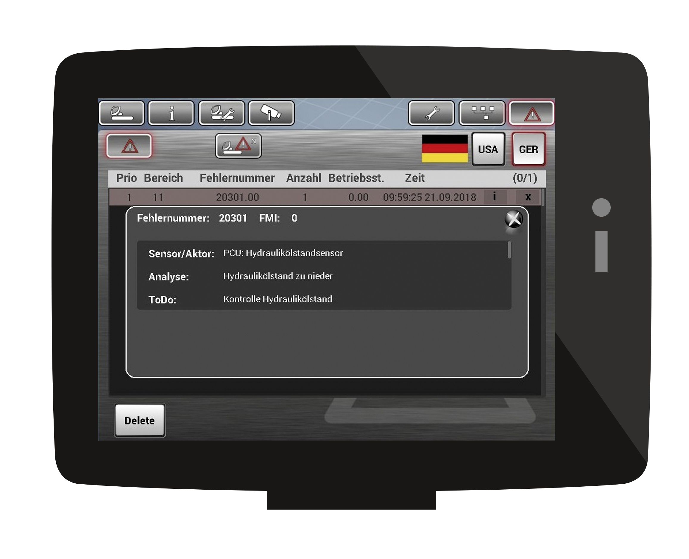
A new feature in error diagnosis is plain text in German and English alongside the code. This applies both to error analysis and to the procedure for rectification, reducing repair work from the outset. A great relief – both for PistenBully customer service and especially for the drivers and technicians in the customer workshop, who are able to detect and resolve many issues independently. Save time and money
A cable length saving of around 25 % has been achieved in the new PistenBully 600 – and that’s with more functions. The complexity of the cabling was minimised, cable harnesses extremely reduced, weight lowered. This also means a 25-% reduction in connectors and fewer sources of error. And saves lots of time and, as a result, costs too.
Two main control units are responsible for the complete logic and intelligence of the vehicle control system: the PistenBully Control Unit “PCU” regulates the working hydraulics, while the PistenBully Drive Management “PDM” deals with the driving. CAN buses are also responsible for the functions in the vehicle: logically grouped, they send commands to the various areas: driver’s cab, chassis and attachment hydraulics, structures like winch or passenger cabin, front and rear equipment. Analysis made easy
Everything used to run through a large hydraulic block, but is now designed “bit by bit” in sections, the individual CAN buses. The functions are no longer interdependent. Technicians would previously have had to understand and look at the complete hydraulic block. Now they can just concentrate on the appropriate section, identifying the relevant valve quickly and easily.
Several so-called RIOs (remote input output) are installed in each CAN bus section: similar electronic components used to record sensor data and to switch and control lights, valves, etc. As they contain no logic of their own, they can be replaced without programming and can be used universally. This means: customers can easily test whether the actual RIO is defective by inserting it in a different place. Tiller example
Three valves lead to the rear from the “BodyCAN”, responsible for the chassis and equipment rack. The tiller is then controlled in turn via the “RearCAN”. While there used to be two connector plugs with up to 50 contacts to facilitate the multifunctionality of the tiller, there is now just one connector, comprising the CANbus and power supply – and using just 5 contacts! The cables for the tiller are installed in the vehicle with no junctions. This means: very clear structures, low vulnerability, really simple error analysis thanks to “on-board diagnosis”. Codes now also in text form
A new feature in error diagnosis is plain text in German and English alongside the code. This applies both to error analysis and to the procedure for rectification, reducing repair work from the outset. A great relief – both for PistenBully customer service and especially for the drivers and technicians in the customer workshop, who are able to detect and resolve many issues independently. Save time and money
A cable length saving of around 25 % has been achieved in the new PistenBully 600 – and that’s with more functions. The complexity of the cabling was minimised, cable harnesses extremely reduced, weight lowered. This also means a 25-% reduction in connectors and fewer sources of error. And saves lots of time and, as a result, costs too.